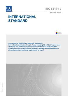
This part of IEC 63171 covers shielded free and fixed circular connectors with 4 ways up to 7 ways for power and data transmission and specifies the common dimensions, mechanical, electrical and transmission characteristics and environmental requirements as well as test specifications respectively.
The connectors described in this document are either equipped with an M12 screw-locking mechanism (styles with M12 in the name) or a quick-locking push-pull mechanism with a size derived from that (styles with P12 in the name) or both mechanisms combined (styles with C12 in the name). For the sake of simplicity, the connectors’ size is denoted as “size 12” in this document.
This document provides multiple mating interfaces each of which is associated with a coding preventing the mating of incompatible male and female connectors. These codings are referred to as “Type x”, where “x” is represented by a Roman numeral.
For all codings, two ways and the additional shield pin, which is intended to be connected to the cable screen, support differential data transmission with frequencies up to 600 MHz by meeting the requirements of Category B, as defined in IEC 63171.
NOTE 1 Connecting the shield pin to the cable sheath is also required for data transmission with 20 MHz (IEC 63171, Category A).
NOTE 2 The connectors are intended to be used for single-pair Ethernet (SPE) according to the following IEEE Standards: 10BASE-T1 (IEEE 802.3cg), 100BASE-T1 (IEEE 802.3bw), 1000BASE-T1 (IEEE 802.3bp).
NOTE 3 Power over Data line (PoDL) power supply according to IEEE 802.3bu can be optionally used for the two ways intended for data transmission, even in addition to the power supply provided through the dedicated power ways.
The individual codings differ by their power transmission capabilities and intents. The additional ways provide for DC power transmission with up to 63 V/16 A and 600 V/16 A or AC power transmission with rated voltage and rated current up to 600 V/16 A (single-phase) or 480 V/8 A (three-phase). See Table 11 and Table 12 for the voltage and current ratings, and Table 5 for the pin assignments for the individual codings.
Some codings feature a PE pin for safety purposes.
The PE pin needs to be connected to all accessible metal parts.
Product Details
- Edition:
- 1.0
- Published:
- 05/01/2023
- ISBN(s):
- 9782832270035
- Number of Pages:
- 38
- File Size:
- 1 file , 3 MB
- Note:
- This product is unavailable in Ukraine, Russia, Belarus


